Besides simple shapes, vampire is capable of generating more complex heterostructures, such as core shell nanoparticles and multilayers. This tutorial explains how to generate a multilayer thin film consisting of two different magnetic materials.
In the input file, specify the dimensions of the total film using
dimensions:system-size-x = <size-x>dimensions:system-size-y = <size-y>dimensions:system-size-z = <size-z>
where <size-x>, <size-y> and <size-z> are the dimensions of the film along the x,y and z directions. The multilayer film is always created along the z-direction, and so <size-z> should be the total film thickness including all layers. For example to define a 10 nm x 10 nm x 2 nm film you should define
dimensions:system-size-x = 10 !nmdimensions:system-size-y = 10 !nmdimensions:system-size-z = 2 !nm
For simulations of thin films, the lateral dimensions are generally much larger than the film thickness. For reasons of computational efficiency it is common to simulate a small lateral section of the thin film while considering the full z-height of the system. In this case you generally want to apply periodic boundary conditions perpendicular to the film normal to avoid artificial edge effects due to loss of neighbours not apparent in real samples. This can be done by defining in-plane periodic boundary conditions in the input file using
create:periodic-boundaries-xcreate:periodic-boundaries-y
 Note
Note
Periodic boundary conditions can also be applied along the film normal, emulating the effect of a periodic magnetic multilayer. However for such simulations the interactions between layers can be quite important and so it is recommended to simulate each of the layers in the structure directly. To assist with this case it is also possible to define a repeating multilayer structure.
In the material file, define material properties for two different magnetic materials making up each of the layers in the multilayer. For example
#-----------------materials:num-materials = 2#-----------------material[1]:exchange-constant[1] = 3.0e-21material[1]:exchange-constant[2] = 1.0e-21material[1]:atomic-spin-moment = 2.0 !muBmaterial[1]:damping-constant = 1.0material[1]:uniaxial-anisotropy-constant = 1.0e-24#-----------------material[2]:exchange-constant[1] = 1.0e-21material[2]:exchange-constant[2] = 2.0e-21material[2]:atomic-spin-moment = 3.0 !muBmaterial[2]:damping-constant = 1.0material[2]:uniaxial-anisotropy-constant = 1.0e-23
Note
Remember that when defining the exchange interactions between materials the values of the exchange constant must be the same i→j as j→i, otherwise vampire will return an error.
In the material file, you now need to define the relative heights of each layer of the thin film using the minimum and maximum height keywords
material[<id>]:minimum-height = <fraction> material[<id>]:maximum-height = <fraction>
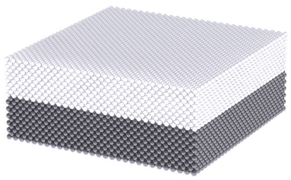
where <id> is the material number and <fraction> is the fraction of the total system size along the z direction occupied by that material in the range 0-1. For example if the first material takes up the bottom half of the film and the second material takes up the top half of the film, in the material file you would define
material[1]:minimum-height = 0.0material[1]:maximum-height = 0.5material[2]:minimum-height = 0.5material[2]:maximum-height = 1.0
Note
Be careful when specifying layer heights. If the heights overlap then the order in which the materials are defined will determine the actual generated structure, and vampire will warn when this is happening.
It is always a good idea to visually verify the generated structure by generating output viewable using rasmol or jmol. The fraction of atoms generated for each material are given in the log file for the simulation.
Vampire can collect statistics for different materials separately, allowing you to investigate the behavior of each layer separately. More details are given in the tutorial on statistics in vampire.
 Caution
If you are using a customised unit cell file (.ucf file), then the definition of multilayer structures will override the material assignment in the ucf file, generally leading to undesired behaviour. More support for complex structures is planned, but at present multilayer structures should be constructed directly in the ucf file.
Copyright R F L Evans 2013-2018